Header_Blue02
Home_Page_Separator03
Integrated_sub-head_Blue02
Listing_Sheets_Title

Information is entered once for each elevation.  Components (heads, jambs, mullions, borrowed lights, etc.) are automatically extracted from the elevations, then engineered, unfolded, and detailed by the system. 
Parts do not have to be described individually.

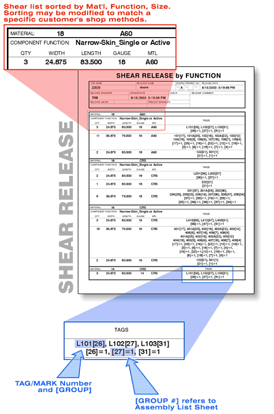
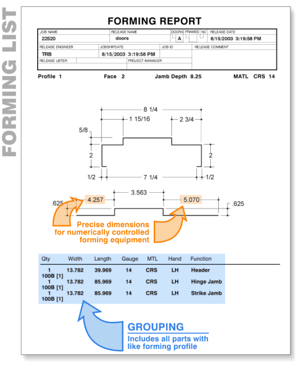
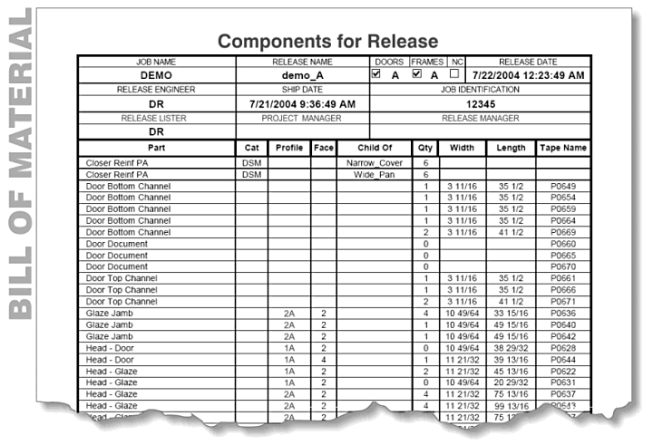
The output includes individual component list sheets, shear lists and brake lists (which are optimized to reduce setups), complete Bills of Material (including all required fabricated parts, reinforcements, hardware), etc.

The following information is limited to Listing Sheet output.

Listing_Overview
Listing_All_Docs
Listing_Elevations_Title
Elevation_Overview02

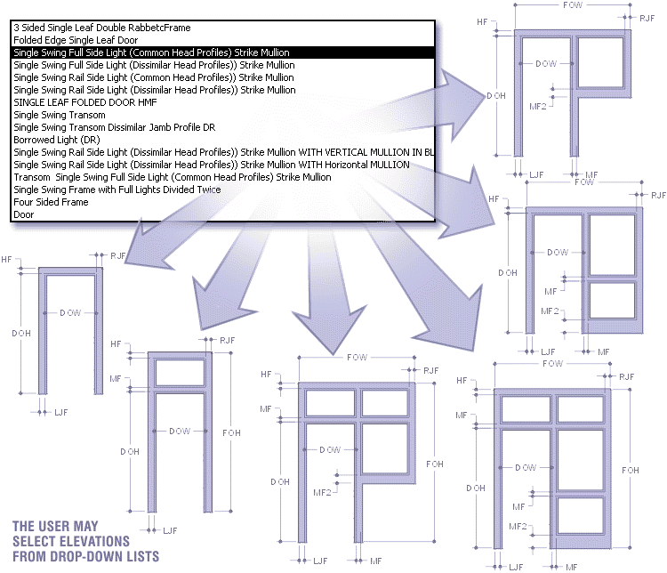
Elevations are included in a job by selecting them from a list.  The basic system comes with a standard set of elevations. A few of these are shown in the illustration above.  Users can easily add new ones as needed.

Elevations in the drop-down represent general frame configurations or layouts. These are all parametric and may be assigned different profiles and an infinite combination of dimensional values. Placing these dimensions is a necessary part of the process in defining an elevation.

The individual parts that comprise each elevation are tracked by the system and the engineering for each component occurs automatically. The way that this occurs is explained in the following section.

GUI_Elevations_ADD
Listing_Profiles_Title

Profile Types and Dimensions:

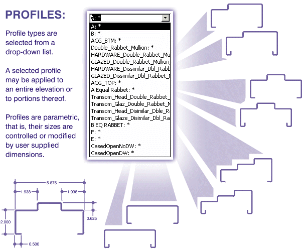
Profiles are also defined in a job by selecting them from a list.  Profiles are flexible, and the list of available profiles represents general geometric configurations or layouts which require dimensions. See the diagram below for a more detailed explanation.

Each profile type & variation (Double and Single Rabbet, Cased Open, Double Egress, Mullions, Drywall, Masonry, etc.) are included in a drop-down list (see below).

The user selects the Profile and supplies the dimensional information. The described Profile is now stored by the system and is available to be applied to elevations (or parts thereof) within the current job.

Profile_selection
Elevation_Components_Title

Once an elevation has been selected, and profiles have been assigned, the user is prompted to provide the information necessary to accurately describe its features. The user inputs are applied to the elevation as a whole, and to the individual elements as well.

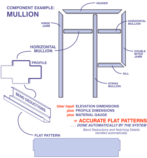
This way, all of the components for each elevation are accounted for in the system, and the specific engineering data for each component is automatically derived as well.   The diagram below illustrates this.

Listing_Exploded_Elevation

All components of an elevation are automatically derived and engineered as shown above.

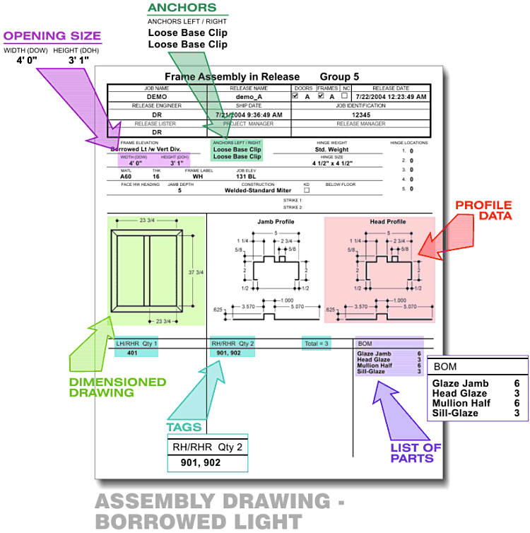
Once specific part data has been derived for each component, the information may be applied to the creation of engineering drawings, List Sheets, Shear Lists, Brake Lists, NC Programs, etc.

Listing_Component_Title

A unique and very powerful aspect of the system is the way that it manages relationships between intersecting components of the various elevations.

In every elevation, the system knows how to apply profile and dimensional information to the various components, and tracks the way those components effect each other.

In the case shown here, the intersection of the sill with both of the mating components is already known to the system. Because of this, the correct geometric and dimensional parameters are applied automatically.

The result? No user interaction is required to define ANY aspect of the sill, or any other component of the elevation.

Of course, the specific elements of each component varies between manufacturers, but once your system has been configured, the parts will exactly match the way you are doing things right now.

And, because the results are predictable, along with drastically reducing the engineering time, errors are eliminated as well.

Relationships_Elevation
Listing_Material_Title

Once your material types and gauges are entered into the system, they may be selected from a drop-down list.  This list is available throughout the system, wherever material must be specified.

Material and Gauge information is fed into the system to supply engineering data that affects the dimensions of the flat-pattern, bend allowance, hardware placement, etc.

Material_List
Listing_Hardware_Spec_Title

HINGES:
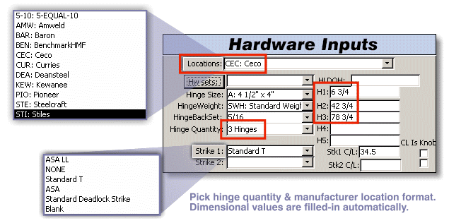
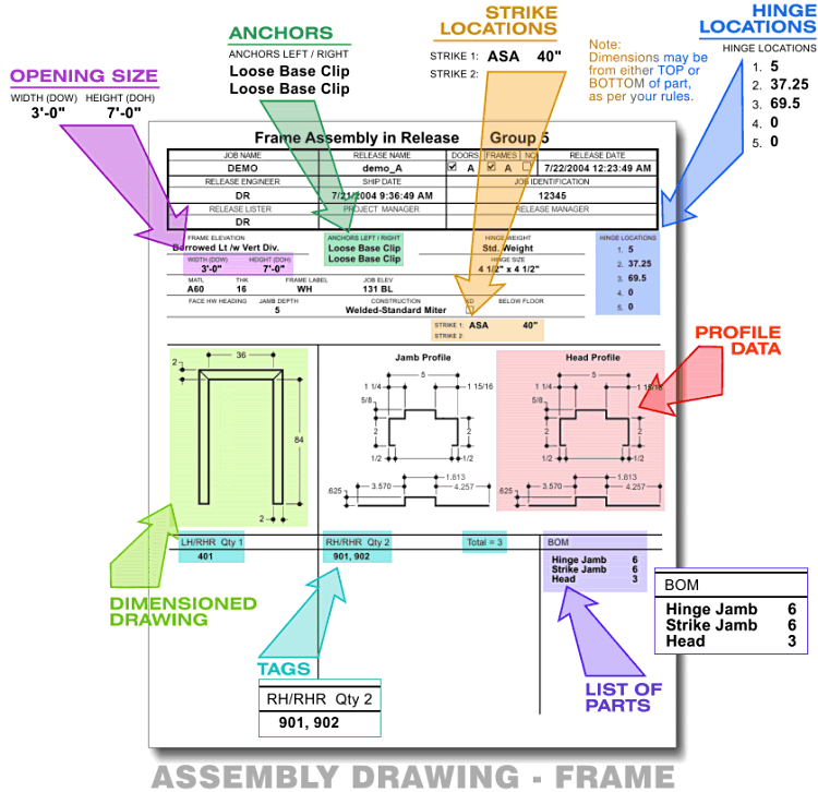
Fields are provided for input of hinge size, weight, backset and quantity. Hinge locations are automatically calculated once the user specifies quantity and manufacturer location format. Values supplied by the system may be overridden by the user if deemed appropriate.

STRIKES:
Input fields for strike types and locations are also presented, as shown below.

Config_screen_Hardware
Listing_Hardware_Sets_Title

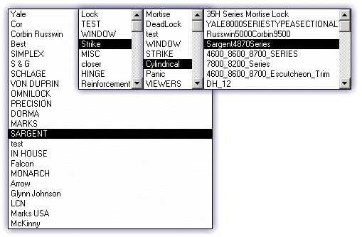
Hardware Sets are drawn from an extensive library of manufacturers’ part numbers.  Once these are selected and applied, the system automatically places them in the flat.

Hardware_Sets
Listing_Sample_Sheets

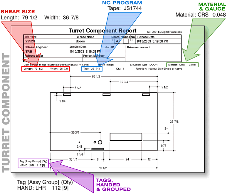
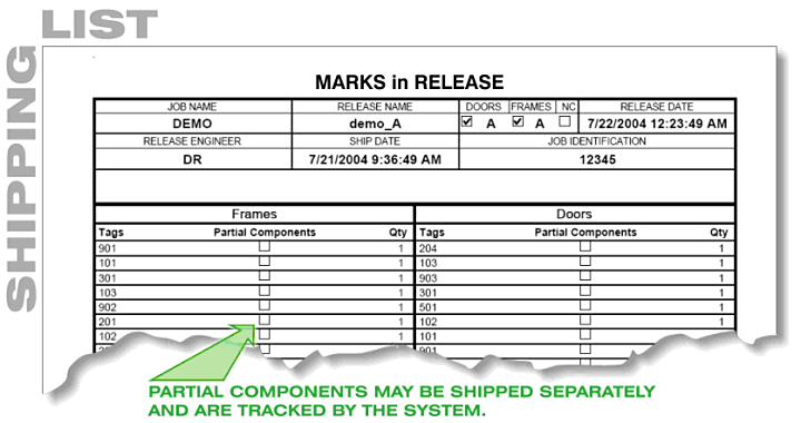
Once the required information is entered, hitting the “PROCESS” button produces all of the required listing sheets & drawings. Details of each type of shop document are shown below.

Drawing_Fab_List_Sheet
GUI_Separator
Shear_List
GUI_Separator02
Forming_List_Sheet
GUI_Separator03
Frame_Assembly_Markup_Window
GUI_Separator04
Frame_Assembly_Markup_Door
GUI_Separator05
Ship_List_Torn
GUI_Separator06
BOM_Torn
[OLD_Listing_Sheets]